


VOL. 17, ISSUE NO. 8 | November 2024
Tech Frontiers


CANADIAN Sculptor Armand Vaillancourt invented the Lost Foam Casting (LFC) process in the early 1950s.1 However, in the mid-1980s, General Motors, USA, started using this technology in commercial production. Complex castings like aluminium engine blocks and cylinder heads are manufactured by this process at lower cost.2,3 It is a cheaper alternative to the conventional sand- casting processes due to its high quality with near-net shape.4 Al–Si–Cu alloy-based LFC is preferred for light-weightiness compared to Fe-based materials.
According to Jiang et al7 and Kim and Lee, in LFC of Al–Si–Cu alloys, porosity forms due to trapped residues and gas is produced from the foam pattern mould filling. Vacuum up to 200 millibar (1atm = 1.01325 bar) on the moulding flask improves (a) the packing of sand grains; and (b) removes vapour and gases formed during casting.
Beeley and Liu et al reported heat transfer phenomena during the LFC process. They observed that the cooling rate of melt in vacuum (a) increases during mould filling, but (b) reduces during solidification. In LFC, the refractory coating on the pattern (a) provides support to the weight of loose moulding sand before the melt fully fills the mould; (b) weight of molten metal to solidify; and (c) resists high temperature of the liquid metal.3,10 Karimian et al11 reported the effect of pattern coating thickness on LFC of Al–Si–Cu. They observed that thinner coatings improved mould filling, quality of castings, and decreased porosity.
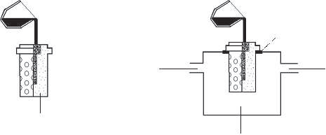
Figure1: Schematic illustrations of casting processes: (a) gravitational (b) vacuum-assisted
| Table1: Chemistry of the alloy | |||||||||||
|---|---|---|---|---|---|---|---|---|---|---|---|
| Fe | Si | Cu | Mn | Mg | Zn | Ni | Ti | Pb | Sn | Cr | Al |
| 1.0 | 7.5-9.0 | 3.0-4.0 | 0.5 | 0.30 | 1.0 | 0.2 | 0.2 | 0.1 | 0.1 | - | Bal. |
EXPERIMENTAL PROCEDURE
All moulds are made of green sand mould because it was necessary to obtain sound castings by using expandable polystyrene (EPS) foam patterns without refractory coating. Simple prismatic shaped patterns are prepared from cutting pieces of an EPS isolation board. The casting trial has been conducted on molten Al–Si–Cu (A380) alloy.
The coating on pattern reduces the gas permeability of mould and increases porosity in castings. The casting made from un-coated pattern shows (a) metal penetration into sand grains and (b) high surface roughness. When the castings are solidified under small amount of vacuum, the gases are removed; so, the porosity is decreased significantly.
Commercial EPS isolation board was used to produce foam patterns. A square prism-shaped pattern (of size 15×15×80 mm) was used for this study. Pieces were cut out from the EPS board by using a fret-saw. Pouring basin-cum-feeder (of size 25×25×20 mm) was also cut from the same EPS board and joined to the main pattern using thermoplastic foam adhesive. Among all the patterns, half of them were coated with water-based commercial refractory dye having high permeability. The dye was made by mechanically stirring refractory particles in water for sufficient time to make homogeneous slurry. Then patterns were dipped into the slurry (once) and then dried at room temperature for 24 hours.
Both coated and uncoated patterns (along with riser-cum-pouring basin) were inserted in green sand moulds (Figure1). Perforated cylindrical stainless-steel flasks were used in mould-making for suction during vacuum treatment. For green sand moulding, silica sand of 50–60 AFS grain size (250–275 µm) was mixed with 5% bentonite and 3% water in mass-fractions.
The mixture was prepared with foundry type sand mixer in 30 min and compacted into flasks around the patterns by foundryman hand-tools.
Al–Si–Cu (A380) casting alloy was melted and superheated to 730°C in an electric resistance furnace with clay-graphite crucible. The chemistry of the alloy is given in Table1.
Green sand moulds, with coated and uncoated patterns, were cast under gravity with and without vacuum-treatment with superheated melt at 730°C. Schematic illustrations of the casting processes are shown in Figure1. Vacuum (approx. 200 millibar) was applied till the end of solidification. After cooling to room temperature, castings were removed from moulds and samples were cut from the tip in 15 mm thickness for characterisation. Density measurement (by Archimedes water displacement) was applied to samples with precision scale apparatus. Then these samples were subjected to grinding and polishing and field analyses were carried with image analyser to determine porosity fraction.
RESULTS AND DISCUSSION
Before evaluation of the experimental results, it must be explained why the green sand moulding technique was preferred. Generally, in the LFC process moulding is carried with dry loose silica sand (unbounded) under vibration. At the time of mould filling, gaseous residues of the foam pattern pass from the refractory coating and flow through the loose sand bed within high permeability. When the coating regulates the gas flow, it creates a barrier between the sand and liquid metal and maintains the shape of the mould until the end of solidification. To make sound castings with uncoated patterns in loose sand mould is not possible; in this situation there is not any layer between the sand and molten metal so the mould absolutely collapses and it will cause to misrun. Green sand moulding technique is necessary for making successful lost foam castings without refractory pattern coating and because of this reason it was preferred for the experimental studies. Another reason is chamber of the vacuum casting machine is not suitable for loose sand moulds.
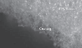
A cross-section of a coated pattern was observed with stereo-microscope to measure average coating thickness and view interface between coating and EPS foam, the image is shown in Figure2.
Figure2: Stereo-microscope image of cross-section view of a coated pattern
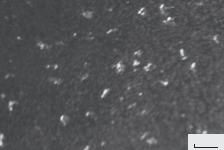
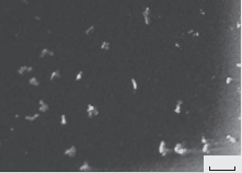
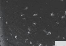
Gas permeability of the green sand is lower than the loose sand. In LFC process, it results in increasing porosity in the final product. However, in this study, experimental parameters like (a) pattern, (b) mould, (c) alloy chemistry, and (d) melt super heat temperature were kept constant and the results obtained from cast specimens were compared among themselves. Figure3 shows the stereo-microscope images of specimens cast (a) with or (b) vacuum treatment on (c) coated or (d) uncoated patterns.
Porosity fractions of these images were calculated with field analysis technique by using image analyser. Both Archimedes density measurements and porosity fraction are given in Table2.
Figure3: Stereo microscope of LFC specimens (a) coated – gravitational, (b) coated – vacuum-assisted, (c) Uncoated – gravitational, (d) uncoated – vacuum-assisted
a

c
b
d
| Table2: Archimedes density measurements and porosity fractions of the LFC specimens | |||||||||||
|---|---|---|---|---|---|---|---|---|---|---|---|
| Pattern type | |||||||||||
| Coated | Uncoated | ||||||||||
| Gravitational | Vacuum assisted | Gravitational | Vacuum assisted | ||||||||
| Density (g/cm3) | 2.68066 | 2.69269 | 2.69075 | 2.69530 | |||||||
| Porosity (%) | 2.63 | 1.50 | 1.99 | 1.26 | |||||||
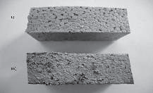
According to the Table3, density measurements and porosity calculations are numerically consistent. The specimen cast with uncoated pattern and vacuum assistance has the highest density and lowest porosity. On the contrary, the specimen cast with coated pattern and only gravitational force has the lowest density and highest porosity. The vacuum treatment creates inter-granular airflow and this enhances gas removal during filing and decrease final product porosity. Measurements have shown that, actually the presence of coating reduces gas permeability and increases porosity fraction. However, pattern coating is a key factor of LFC process. One of the advantages of LFC process compared to conventional sand casting is owing to the refractory coating; surface shape and quality of castings are almost identical with foam patterns. Figure4 shows the photograph of the LFC specimens cast with coated and uncoated patterns.
Beaded structure of the EPS foam is clearly seen in casting with coated pattern. However, surface finish is very rough in casting with uncoated pattern. Liquid metal penetration into sand grains happens during the filling when the uncoated patterns are used. While the refractory coating is being a barrier between the sand and liquid, on the other hand it constitutes the surface shape of metal. Furthermore, vacuum treatment can cause regional liquid penetration and surface roughening.
Figure4: LFC specimens (a) cast with coated pattern (b) cast without coated pattern
Conclusions
- Normally, loose sand moulding is used in conventional LFC process. However, green sand moulding is necessary to make sound castings using expendable foam patterns without coating.
- Small amount of vacuum (applied during freezing) favours (a) gas removal, and (b) decreases porosity fraction of the LFC products. But in some cases, it causes possible local metal penetration and rough surface finish.
- However, the refractory coating is necessary while using loose sand moulding, it decreases gas permeability and effects porosity fraction of the castings.
- Refractory coating has the effect on surface property of castings. Cast parts reflect the same surface shape and quality of the foam patterns when the refractory coating is carried out.
References
- https://en.wikipedia.org/wiki/Lostfoam_casting
- Fan, ZT and S Ji. J. Mater. Sci. Technol., 2005, vol.21, p.727
- Liu, XJ, SH Bhavnani, RA Overfelt. J. Mater Process Technology, 2007, vol.182, p.333
- Li, JL, RS Chen, WKe. Trans. Nonferrous Met. Soc. China, 2011, vol.21, p.761
- Jafari, H, MH Idris, A Shayganpour. Trans. Nonferrous Met. Soc. China, 2013, vol.23, p.843
- Jiang, W, Z Fan, D Liao, D Liu, Z Zhao, X Dong. Mater. Des, 2011, vol.3, p.926
- Kim, K, K Lee. J. Mater. Sci. Technol., 2005, vol.21, p.681
- Beeley, P. Foundry Technology Second Edition, Oxford: Butterworth-Heinemann, 2001
- . Liu, ZL, QL Pan, ZF Chen, XQ Liu, J Tao. Trans. Nonferrous Met. Soc. China, 2006, vol.6, p. 445
- Karimian, M, A Ourdjini, MH Idris, H Jafari. Trans.Nonferrous Met. Soc. China, 2012, vol.22, p.2092
This paper was originally published in the Souvenir of 72nd IFC, held during 3-4 February 2024 in Bangalore. Published here with the kind permission of the publishers of Indian Foundry Journal, Vol.70, Issue6, June 2024
The author can be contacted at sr@kejriwalcastings.com
© Copyright , All rights reserved. Design by Andreal