


VOL. 18, ISSUE NO. 10 | January 2026
Tech Story


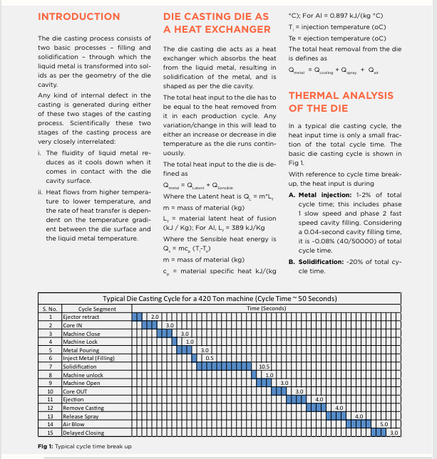
While the heat removal is through‑ out the cycle time, i.e., 100% of the 50‑second cycle, by means of inter‑ nal die cooling and heat loss during spray and air contact.
The key purpose of thermal balanc‑ ing dies is to remove the maximum heat during the metal solidification process as quickly as possible. With this consideration, heat removal during spray and air contact can be minimised.
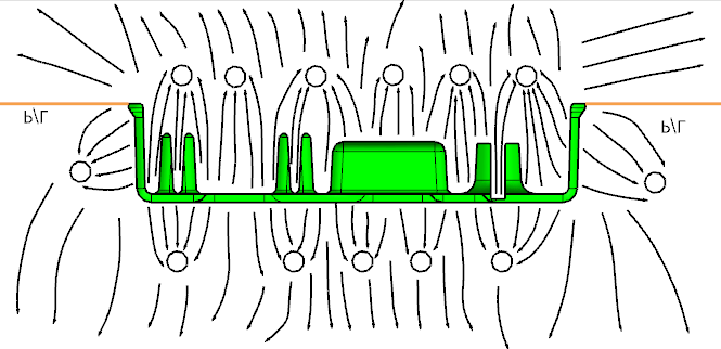
Fig 2: Die cross section to study the heat input in different regions
As we see from the given equation, the heat input depends on the mass of the material poured in the die. At the same time, the volume of met‑ al in different regions of the cavity (depending on the casting geome‑ try) will give different heat inputs to respective regions of the die (Refer to Fig 2).
The heat input to each region of the die during each production cycle must be removed within the given cycle time. If the heat input is more in one region and less in another re‑ gion but the heat removal through the internal cooling and spray is uniform across these regions, it will lead to a continuous tempera‑ ture increase in the high heat input area and a continuous temperature decrease in the low heat input area during each cycle. The die tempera‑ ture will never reach an equilibrium.
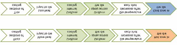
Fig 3: Understanding of the heat flow thru different die regions
Hot zones and cold zones exist in the same region of the die cavity.The above phenomenon leads to various types of casting defects which may be due to the hot condi‑ tion of the die or the cold condition of the die.To optimise and balance the ther‑ mal conditions of the die, the fol‑ lowing actions are required:
- Strong and effective internal cooling for hot zones
- Strong and effective heating for cold zones
These conditions are contradic‑ tory in nature and are difficult to achieve in the same die with con‑ ventional cooling designs. The heat input to the die and heat output from the die must be balanced re‑ peatedly in every production cycle.
This requires:
- Thermoregulation units
- Strong internal water cooling at high pressures with an intermittent cooling cycle
- Jet cooling
- Application of additive manufac‑ turing for 3D profile cooling
- Customised die coat spray heads
Use of thermoregulation units pro‑ vides both heating and cooling to the die to maintain the required die temperature at different regions of the die. Both water‑ and oil‑based thermoregulation units are available to monitor and balance the heat in‑ put and heat output from the die.
Strong internal water cooling at high pressures with an intermittent cooling cycle, usually run at a mini‑ mum of 5 bar water pressure to re‑ move the maximum heat as fast as possible from the hot zones during solidification. The cooling water is circulated through the die only for a small part of the cycle time during solidification of liquid metal. This is controlled by a solenoid valve to start and stop the water flow ev‑ ery cycle as per the temperature requirement in different zones of the die. This can be applied to inter‑ nal channel cooling as well as spot cooling in the die.
Use of jet cooling to achieve a strong localised cooling effect. Jet cooling is used at 15~20 bar water pressure.
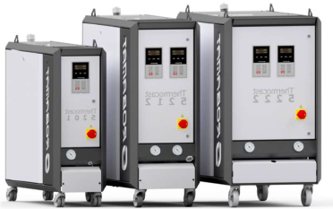
Fig 4: Water OR Oil based Standard Thermoregulation units
USE OF ADDITIVE MANUFACTURING FOR INTERNAL COOLING
This is the latest technology for ef‑ fective internal cooling and achiev‑ ing a good thermal balance in the die, increasing die life and improv‑ ing casting quality. The 3D profile cooling channels are made internal‑ ly in the die parts to reach the areas where conventional cooling (line cooling / spot cooling) cannot be provided.
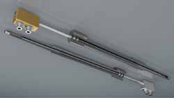
Fig 5: Typical Jet cooling arrangement in a core pin
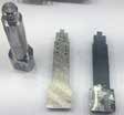
Fig 6: 3D Profile internal cooling using Additive Manufacturing
The objective of using the die coat sprays in the dies is to provide a protective layer to protect the die surface from direct attack of aluminium metal. In this process, a lot of heat from the die is absorbed by the spraying water mixed in the die coat depending on the spray and blowing time. Customised spray heads can be used.
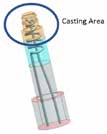
Fig 7: Dedicated customized Spray Heads
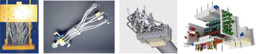
Fig 7: Dedicated customized Spray Heads
A. to provide extra cooling to the hot zone areas by providing ex‑ tra spray nozzles
B. to reduce the cooling effect in the cold zone areas by reducing the number of spray nozzles
OPTIMISATION OF PROCESS PARAMETERS
In the production process, die cast‑ ers employ standard shop floor practices to address defects specif‑ ically caused by cold zones in the die:
I. Increase the 2nd phase speed – the use of the higher 2nd phase speed leads to reduced fill time; hence, the temperature drop during cavity filling is reduced, and partial results are achieved without addressing the root cause.
???? Image 10: tech_story_p71_img0.png
Replace REPLACE_WITH_CDN_URL_10
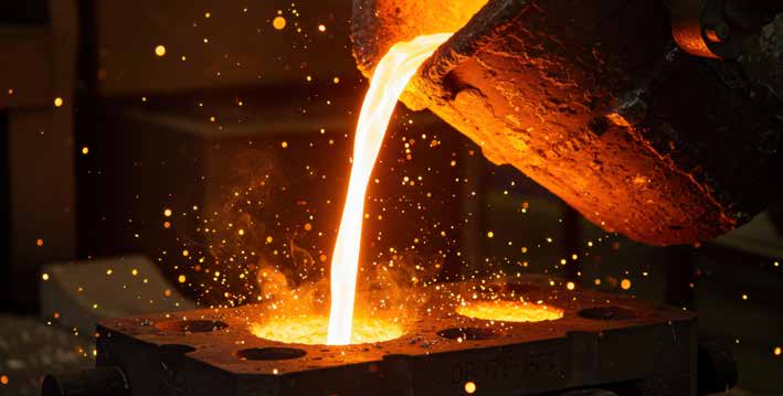
II. Increased Intensification pressure – the desired cast pressure does not reach to the thick mass zones due to fast freezing of metal in nearby thin sections/cold areas. The high intensification pressure is used to press the cold metal and give partial results without addressing the root cause.
???? Image 11: tech_story_p71_img1.jpg
Replace REPLACE_WITH_CDN_URL_11
Both these actions result in exces‑ sive stress on the die and on the machine, leading to frequent break‑ downs during the production pro‑ cess, affecting the casting quality and life of the die as well as the ma‑ chine.
CONCLUSION
Use of different solutions as discussed above leads to better die thermal balance, reduced casting defects, reduced cycle time resulting in higher productivity, less thermal stress in the die resulting in better die life and delayed heat checks, and minimum die and machine breakdowns.
References
Various NADCA publications, information available in public domain and Case studies at TechSense Engineering Services
© Copyright , All rights reserved. Design by Andreal